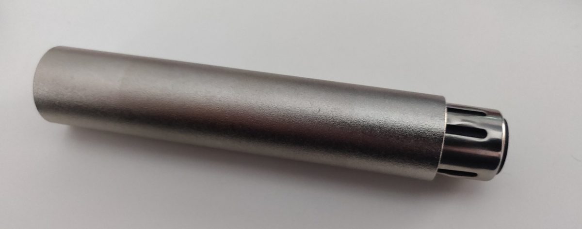
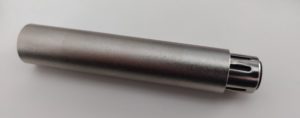
Several well known audio/electronics distributors sell inline XLR audio attenuators. Typical values sold are -10 and -20dB. I had a need for -30dB so took one apart to change the internal resistors.
The theory of operation is that since balanced audio has two equivalent signals of opposite phase, a resistor tying hot and cold together will reduce the overall magnitude of the audio signals. A common improvement is to create a ‘H’-pad which uses five resistors to assist with impedance matching.
A simple diagram showing the arrangement of a ‘H’-pad:
Hot in — r1 -|- r2 — hot out
. r3
Cold in — r1 -|- r2 — cold out
I was surprised to find that these so called balanced attenuators contained all the correct resistors but in a nonsensical arrangement (Unfortunately I didn’t take a picture). The closest thing they resembled was a ‘T’-pad which is commonly used as an unbalanced audio attenuator (resistor from audio to ground).
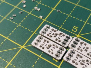
To give the attenuation value I desired and generally improve the quality of the device, I designed a small PCB that would fit inside the XLR shells. It uses 0805 resistors to conserve space, the hot and cold are combined in a ‘H’-pad circuit with ground being passed from one end to the other. Varying the resistor values gives different amounts of attenuation. A useful calculator can be found here.
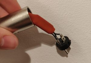
Overall, the final result was much better than the original. The heat-shrink worked well to prevent shorts to the outside casing.